|

Reference Guide
|
|
How to / Using Options
Adobe PostScript 3 ROM Module
 Installing the ROM module
 Removing the ROM module
Installing the ROM module
Follow these instructions to install the optional Adobe PostScript 3 ROM module:
 |
Turn off the printer.
|
 |  |
Warning:
|
 |  |
To avoid electrical shock, do not attempt to install a ROM module unless the printer is turned off.
|
 |
Unplug the printer's power cord from the electrical outlet.
|
 |
Remove all interface cables from the interface connectors.
|
 |
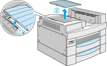
Open the top cover of the face-down tray.
|
 |
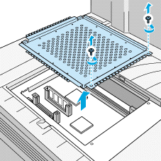
Loosen the two retaining screws and remove the plate.
|
 |  |
Note:
|
 |  |
To avoid losing the retaining screws, do not remove them completely from the plate.
|
 |  |
Warning:
|
 |  |
Avoid touching electrical components that are exposed after you remove the plate. They may be very hot if the printer has been in use.
|
 |
Identify the slots for ROM modules. Their relative locations are as shown below.
|
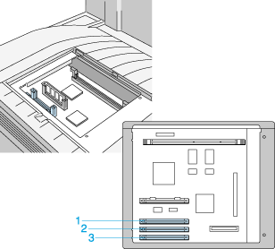
1. slot A
2. slot B
3. slot C
 |
Hold the ROM module in the following orientation, then insert the ROM module into slot A.
|

 |
Push the ROM module into the slot evenly until the button comes up.
|

 |
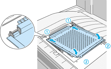
Return the plate to its original position. Place the two outside tabs of the plate under the edge of the opening with the inside tabs on top of the edge.
|
 |
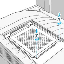
Push the plate down into place. Then fasten the two retaining screws that you loosened earlier.
|
 |
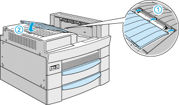
Gently replace the top cover until it clicks shut.
|
To confirm that the Adobe PostScript 3 ROM module is installed correctly, print a status sheet. If PS3 is not listed as an installed emulation on the status sheet, try reinstalling the module making sure that it is securely fastened to the ROM slot.

[Top]
Removing the ROM module
Follow these steps to remove the Adobe PostScript 3 ROM module:
 |
Turn off the printer.
|
 |  |
Warning:
|
 |  |
To avoid electrical shock, do not attempt to remove a ROM module unless the printer is turned off.
|
 |
Unplug the printer's power cord from the electrical outlet.
|
 |
Remove all interface cables from the interface connectors.
|
 |
Open the top cover of the face-down tray.
|

 |
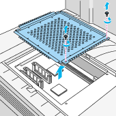
Loosen the two retaining screws and remove the plate.
|
 |  |
Note:
|
 |  |
To avoid losing the retaining screws, do not remove them completely from the plate.
|
 |  |
Warning:
|
 |  |
Avoid touching electrical components that are exposed after you remove the plate. They may be very hot if the printer has been in use.
|
 |
Push down the button on the side of the ROM slot until the module comes up.
|

 |
Pull the ROM module up and out of the slot.
|
 |
Return the plate to its original position. Place the two outside tabs of the plate under the edge of the opening with the inside tabs on top of the edge.
|

 |
Push the plate down into place. Then fasten the two retaining screws that you loosened earlier.
|

 |
Gently replace the top cover until it clicks shut.
|

 |
Reconnect all interface cables.
|
 |
Plug the power cord into an electrical outlet.
|
 |
Turn on the printer.
|

[Top]
| Version 1.00E, Copyright © 2001, SEIKO EPSON CORPORATION |
Installing the ROM module
Removing the ROM module